This page contains detailed logs written over the course of the project to show the progression of the project during the quarter and the steps our team took during the course of this project.
Progress Logs:
Meeting Team 10/3/19 and Scheduling Interview:
During the second class session I met with my team for the first time. We exchanged contact info and discussed potential times during the week we would all be available to meet. Within our hardware-focused team we brainstormed and drafted possible interview questions for our first interview with project partner, Phillip Krieg.
We decided that the software team and hardware team should conduct the initial interview with him together because we acknowledged that the eight of us would be working closely together on the same project as well as all working closely with Phil.
The software-focused team made a Google Doc on Sunday, 10/6 with interview questions and different members from each team were able to sign up attend the interview. The eight of us agreed that it would be a good idea to send no more than four team members to meet with Phil Krieg for the first time.
Jack emailed Phil and scheduled the interview for Monday, October 7th, at 2 PM in the Forge Garden.
Conducting Research and Project Update 10/15/19:
Currently the Hardware team and Software team have not been in a lot of contact since we are working on our separate components of the final product. I plan to talk with the Software team in class on 10/17 to discuss the power needs of the raspberry pie they will be using so that the hardware team can order the right sized solar panel. A
After the hardware team decides what subassemblies we need to build for air final assembly we will discuss materials we want to use. The materials we use need to be durable and weatherproof but also not expensive. The purpose of our product is to be cost effective and efficient.
The hardware team divided Research among the four us. Eva is in charge of taking measurements of the beehive in the Forge Garden and researching different components we may need to implement in our product. Joce is responsible for researching solar panels and finding the smallest possible size we can use for the project needs. Ethan is researching mechanical scales to discover how we can implement our own in our hive scale. Thea is investigating different components of existing commercial hive scales that we may want to include or exclude from our final product.
Research on Potential Designs 10/22/19:
During the last five days since Thursday's class, I have spent one to two hours a day doing research on different type of autonomous scales and different potential solutions. Along with research I have also reached to my other engineering classmates for advice and new input on the project.
Many beekeeping forums and hive monitoring forums show that most DIY hive scales use load cells to measure the weight. However, it is also true that load cells have a creep value and are not meant to be under a constant load. Although load cells are most commonly used for this application to connect to a raspberry pie I do not think this is a good long term solution. Next I did a lot of research on mechanical scales and autonomous mechanical scales. Open Hive Scale is a company that sells a hive scale kit that uses a mechanical scale with a motor and optical endstop. The motor in the scale moves a weight to counterbalance the load. Based n my knowledge I am assuming that the optical endstop is triggered to stop the motor when the mass is counterbalanced against the load of the hive. This idea is more complex, but I like the fact that is accurate and can last under a constant load. The other problem with this idea is that I am not familiar with how to find the weight of the load after it is counterbalanced. This probably needs another sensor to find the distance of the mass from the fulcrum to calculate the weight of the load and communicate it to the raspberry pie.
Another option I looked into was a hydraulic pressure system. One where we could measure the pressure of a fluid under the load of the scale. Unfortunately I feel that this may be too complicated and not the right fit for this project.
I know that my team and I would be more successful using load cells than we would trying to create an accurate mechanical scale using a motor and some sort of endstop. Also, building a scale using load cells and other materials we may already own will help us stay under budget. After all the goal of this project is to have a relatively cheap but efficient hive monitoring device.
When asking some of my friends about their thoughts on the project one recommended that I use some sort of motor or piston to lift the hive off of load cells and then lower the hive onto the load cells every twenty-four hours to take a weight measurement. At first I did not love this idea because it means moving the hive, but I realized that it could be a very small displacement of less than an inch as long as the entire load of the hive is transferred onto the load cells when a measurement was taken.
Right now this is my favorite design idea since it uses the efficiency and accuracy of load cells without causing them to deteriorate quickly.
Second Meeting with Phil 10/24/19:
After meeting with Phil and not receiving a lot of positive feedback on the design idea I feel stuck on what to do next. The hardware team went to talk to Dr. JAK after meeting with Phil to see what advice she could give us. She said that if we have done a lot of research and we know what we can do within our budget then we should try and build a prototype of our idea for proof of concept. She also said that we should find the three most popular commercially produced hive scales and do a pros and cons list on each method the companies use. Then we can present this research to Phil and explain to him why we think our design idea will work and meet his needs.
We decided that we would go ahead with prototyping our design idea but continue doing research into other beekeepers methods and experiences with hive scales.
Purchasing Materials and Prototyping 10/31/19:
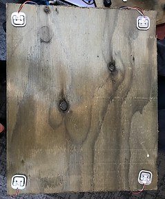
On Thursday during class the four members of the hardware team decided to go to Home Depot to buy supplies for the hive scale. We need wood for the frame, screws, and metal squares for the load cells to sit on. The four of us spent about an hour in Home Depot taking to Sale's Representatives and looking around to decide what exactly we needed to buy. We ended up purchasing a blank by blank by blank piece of pressure-washed wood to build the main part of the scale out of. We also purchased a pack of screws and 4 small slabs of steel to screw on to the wood platform for the load cells to sit under.
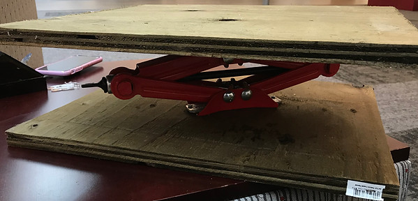
On Thursday night I built the scissor jack for the prototype put of the parts I 3D printed earlier this week. The scissor jack is not very stable, but it will work for the prototype to prove our concept. Dr. JAK gave me an Arduino, breadboard, jumper wires, a gear motor, and a dual h-bridge motor driver to borrow for prototyping. Over the weekend I was able to build a simple circuit with the motor and program it to move both clockwise and counterclockwise for a certain amount of time. For testing the circuit I set the motor to turn counterclockwise for five seconds, brake for five seconds, and then turn clockwise for 5 seconds before resetting. The next step will be using a rubber band, that will act as a V belt, and attach it to the screw that drives the scissor jack and the motor. This allows the motor to move the scissor jack up and down, therefore lowering or lifting a platform with a load.
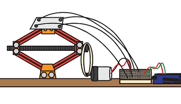
Image 4: Prototype Design
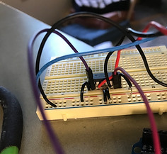
Image 5: Gear motor circuit with Dual H-Bridge
Team meeting and status update preparation 11/5/19:
Today my team met to make our powerpoint for our status update presentation. Since Phil is out of town this week, Dr. JAK will be videotaping our presentation to send to him. I am a little nervous for the status update because we are nearing our project deadline and we want to make sure that our team has made the right amount progress and in the right direction.
After our meeting I contacted the software team to see if I could give them the load cells and Arduino to work with. I was not able to upload the load from my laptop because I did not have access to a file I needed to download from Github. I met with the other team at eight to drop off the materials and explain the work I had done and how to set up the load cell circuit. I also showed them resources available through SparkFun to help set up the circuit and program the load cells.
Before the presentation I need to make an attachment to the gear motor to loop a rubber band around it and the driving screw on the scissor jack so that when the motor turn it also turns the screw and moves the scissor jack. I want to use a thick rubber band for the prototype because it is elastic and needs to expand as the scissor jack moves upward.
Joce went to the Maker Lab this week and used the laser cutter to cut pieces of acrylic and make a model beehive for our prototype. the model will sit on top of the 3D printed scissor jack and hopefully show that the hive is minimally affected bu the minor movements of the jack.
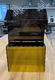
Image 6: Joce's model beehive made of acrylic
Bringing the teams together and learning from critique 11/17/19:
On Sunday, members from both the hardware and software team met to connect the load cells to the Pi and test the code. Thea, Joce, Remy, Dwight, and I met in Healey and worked on the circuit for two hours. Remy and Dwight worked on the code for a total of 5 hours n Sunday but were struggling to fix errors in the program and upload to the Pi. We also realized that we need male-female jumper wires to connect our circuit to the Pi and we only had male-male wires from when we were using the Arduino. We were able to build the circuit following the guide on SparkFun using the load cell combinator and amplifier.
While we were working, a professor approached us to ask us about the 3D-Printed scissor jack. They mentioned that they had assigned students to design, print, assemble a scissor jack in a past class and was curious as to where we found our design. I informed them that we got the design from Instructables and told what we were using it for in the project. the professor than told us that our idea was terrible but laughed it off and later offered to give some advice.
On Monday, I met with the professor because I was interested in their advice and wanted to know the reasoning behind their initial opinion. After talking with them for awhile, they made it clear that we actually did have a good idea and had thought outside of the box with our design but that it was maybe a little more complex than it needed to be.
They agreed with me that we need to test the load cells and creep over a few days with a known weight and the affects of temperature by leaving the load cells outside. Going into that meeting I felt a little defeated, but after I left I realized that I have done a lot of work this quarter and I have learned a lot, and I should be proud of the progress we have all over the last eight weeks.
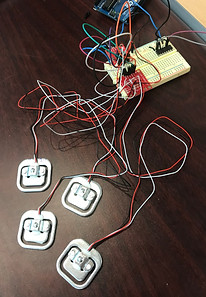
Image 7: Load Cell circuit
Final Design:


Problems in the Final Week 12/4/19:
The Monday after break, I met with Joce to get the load cells and Arduino from her. After I finished class for the day I met with Dr. JAK to get a new Arduino and talk to her about the issues we had. She gave me a new Arduino and a transistor to try and use with the motor.
I was hoping to get the motor working that night and see if the load cells could still control the motor. Unfortunately, the wiper motor was stilton working in the circuit because it was drawing to much power from my laptop. The USB port on my laptop was disabled and the Arduino shut off. I realized I needed a 9V external battery to use with the motor and Arduino. That night, the code was uploading to the load cells but they were only reading zero pounds no matter how much weight was on them.
On Tuesday I purchased a 9V battery and connected it to the h-bridge and motor circuit. The wiper motor still did not work.
Seven of us met on Tuesday night to work on our final presentations and fix the load cell code. The load cells were still reading zero pounds or randomly reading large negative numbers.
That night we left not really knowing what to do and the team member that has the most coding experience was not at the meeting.
On Wednesday I took the load cells, Arduino, and motor to Dr. JAK to sow her the issue and see if she had any advice. We worked for an hour but the load cells were still unresponsive. She told me to stop wasting energy on the wiper motor and to just use the smaller gear motor because it has been working well. When we tried to connect the h-bridge and load cels to the Arduino a new problem occurred. The Arduino shut off every tome the dual H-bridge was connected. Before we could figure it out, she had to go to a meeting, and I headed to the Maker Lab.
I was able to solder wires for the first time and connected all the load cells to the combinator. I also 3D printed gears for the motor/scissor jack connection.
Later, the hardware team met to attach the motor and load cells and run the code. We realized that without the load cells working we have nothing to show because we can not show the motor responding to the load cells. I also realized that the software team never finished the code to run the motor in the opposite direction and lower the scissor jack. I tried contacting the software team, but they were not very helpful and did not add or fix anything.
The hardware team feels disappointed and embarrassed because we can not show the work we have done and show our final prototype working without the help of the software team.
Since the presentation is on Thursday, we decided to show the motor controlling the scissor jack and try and give the load cells to the software team in hopes of a last minute fix.
Initial Interview with Phillip Krieg 10/7/19:
Jack Guillet and I are the two team members who attended the interview today. We both introduced ourselves to Phil for the first time and were able to see the two Santa Clara University unoccupied beehives that we will be using for the project this quarter.
Jack and I took turns asking questions and I took notes on Phil's answers. Phil showed us the two unoccupied hives and we were bale o observe the base of the hive and the some pictures of the inside and outside of the hive.
After we finished the interview Phil had Jack and I put on beekeeping suits and showed us the occupied hives in the Forge Garden. We were able to see how the bees had occupied the different frames and we got to try raw honey directly off of one of the frames.
After the interview I met with the other hardware team members to catch them up on what was discussed in the interview and we also made a tea contract for the quarter that we all signed.
The Interview and Contract can be found under Formal Documents

Image 1: Inside the 1O frame unoccupied beehive
First Progress Report to Dr. JAK and Forge Garden Visit 10/17/19:
Today The team met with Dr. JAK and Sally to give them an update on the project and ask questions. Dr. JAK told us that since there are so many ways we can go with the design of the scale, we need to do more research on the pros and cons of each idea. I think that we need to have our design by the end of week five so that we can start building a prototype in time for the progress presentation during week 7. Ethan found some beekeepers online that adapted the load cells from a Wii Fit Board to work in their hive scale. We all like the idea of using load cells from an item one of us may have because it will be cheaper and we know that the load cells in a Wii fit board can measure the weight of human which means it will be able to handle the weight f the hive.
After talking to Dr. JAK the four of us went to the Forge Garden to take measurements of the hive and insert the base of the hive. We unstacked one of the two unoccupied hives to observe the base. The base is an open frame that Phil built to add a ramp up to the entrance of the hive for bees to use. The four of us got excited because we think that we might be able to build our hive scale within in this already existing frame that the hive sits on.

Imagine 2: Existing base the hive sits on
Team Meeting and Design Discussion 10/22/19:
Today I met with my team to discuss my design idea and talk about the plan for the rest of the week and Thursday's class. The four of us met in Heafey for an hour and I sketched my design out and the whole team liked the idea. The current design idea we have is to build a base frame for the hive to sit in that is an about 1 inch thick on each of the four sides. In the center of the frame will sit a platform with 4 load cells on it. Th platform will be sitting on a scissor jack powered connected to a gear motor. That way the load cells will not be under a constant load and break or lose accuracy. However, when the program runs every twenty-four hours the motor will run and lift the platform until the entire weight is on the load cells, The motor will be triggered to stop when the load cells monitor that the weight on them is no longer changing. After the load cells take this weight measurement the motor will run in reverse to lower the platform back to its main position and the weight of the hive will return to the base frame. The exciting aspect of this idea I that the lifting of the hive may not even be noticeable to the human eye since it will only take a couple millimeters of lifting to transfer the weight from the frame on to the platform with the load cells.
The next step is bringing this idea to the software team on Thursday and talking abut making a sample program to test o a prototype to see if this will work the way we hope it to. I am hoping that we can 3D print a small scissor jack and borrow a gear motor and Arduino for Dr. JAK to build the circuit and test it. Ethan's mom is mailing us his hold Wii For Board, so we will be able to recycle the four load cells from that. We want to use these load cells because we know that the Wii Fit Board was made to measure a human up to 300 pounds and they re accurate to a tenth of a gram which is perfect for this application.
I am very excited to meet with Phil on Thursday and run this design by him so that we can get to work on prototyping.
More Research and 3D Printing Parts for Prototype 10/29/19:
As I continued doing research I discovered a forum on Arduino of beekeepers discussing different problems they encountered while trying to build a DIY hive scale. Out of eight pages of posts the majority of posts costed of beekeepers complaining about he difficulties of using load cells under a constant strain. Many discussed how the load cells were accurate at first but after a few days the values lost accuracy due to creep properties. One beekeeper had the same idea we had to use a motor to lift load cells to the base of the hive to take a measurement, but he never followed through with trying to build it. One person commented tat the creep value could be ignored because you could monitor the change in weight by taking the difference between each measurement. This comment confused me because I know that we could find the change in weight using this method, but we also want to know the exact weight of the hive and ignoring the creep wont allow us to do that. Some beekeepers mentioned that they tried to recalibrate the load cells each time they wanted to take a wight measurement. Unfortunately recalibration requires a known weight and if the hive is constantly on the scale we can not recalibrate it with a known weight. After reading this forum I realized that trying to use just four load cells under constant weight of the hive will fail to give accurate measurements after a few days in use.
I hace tried to look more into companies that sell hive scales but it is difficult to gather a lot of valuable information on their methodology from their websites. In the next few days I plan on calling some of the companies to learn more about how expensive their scales are and potentially what type of load cells they use, especially if they are just using load cells and no other mechanism.
Today I also 3D printed parts from Thingiverse for a small scissor jack that we can assemble and use for prototyping to hopefully prove our idea.
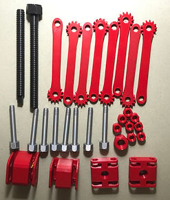
Image 3: 3D printed parts for scissor jack prototype
We also ordered four load cells, a load cell combinator, and an amplifier from SparkFun.
Status Update Presentation 11/7/19:
Dr. JAK filmed all of the status update presentations to send to all the community partners that could not be there, including Phillip. The hardware and software teams presented separately since we have been focusing on different aspects of the project. Our team discussed our prototype and what we have left to do for the project. We also presented some research on commercially produced hives to highlight the key features we were adapting and not using. We also showed some sections of posts on the Arduino forum for beekeeping to understand what other beekeepers had done to measure the weight of the hives. We presented this information to show the thinking behind our design and the research we conducted to get to our current design.
I think that we did a good job at presenting all the information we needed to and proved that we have the knowledge we need to find this project and a plan.
The software team presented after us and they discussed the work they have being doing with the code we will be using. The main robes right now is that we still do not have the raspberry pi which we need to finish prototyping,
Plan and Raspberry Pi Update 11/12/19:
On Tuesday our team met to finish our second Design Reflection and talk about the raspberry pi situation. The second design reflection is about different organizations or relations that have an effect on our project. Earlier in the week I was in contact with one of the software team members about the Raspberry Pi. They have tried contacting the company to find out when our Pi is being delivered but so far they do not have any luck. I am worried that it might never show up on time, or it will show up too late and we won't be able to finish prototyping before trying to build our final design. The software team might have to look into using an Arduino instead but that requires code for the Arduino which we do not have right now. Our team decided that we will wait anther week for the Pi and if it docent come by then we will order our remaining parts and start building the final assembly. On Thursday during class we want to cut the wood we bought and start assembly the platform that will make up our scale.
Progress 11/14/19:
The Raspberry Pi arrived! As it turns out the Pi had been delivered to campus at least a week ago but was put in the wrong mailbox. Dr. JAK ordered a second one earlier this week and then she received both of the Pi's on Thursday.
During class on Thursday we talked to Dr. JAK about our progress and concerns we have for the project. We know that we still have a lot to do, but we are excited that the pi is here because now we can really hit the ground running and continue progressing to our final project. We decided that we want to have a fully functioning prototype by the end of Week 9 so that when we return from thanksgiving break we can assemble the final version.
While the rest of my team went to Ethan's house to cut the base and load cell platform for our final assembly, I went to do research on motors to find one that has a strong enough torque to lift 400 lbs. I decided to research what kinds of motors people se to make their own automatic car jacks. It turns out that a lot of people use old wiper motors from their car and weld it to a normal scissor jack to make an automatic scissor jack. After realizing that a used 12V wiper motor Ould be relatively cheap and good fro this application I called two junkyards in Santa Clara to see if they had any. I was told that a used motor would be $45, but I knew I Ould find one cheaper. I went on to Facebook Market place and found someone in Santa Clara selling a wiper motor from a 240z Datsun for $5. I immediately contacted him and am working on getting the motor from him.
Once we have the motor, I use its 6 wires to build to control its direction and speed.
Pi Problems 11/19/19:
On Tuesday, all eight of us worked together in Heafey. We struggled to to get the code uploaded to the Pi. Remy's laptop wasn't responding and Dwight thought he was able t upload the code but noting happened. We were able to run a similar code using the Arduino and got the motor to run when a load was applied t the load cells. We still need to change the calibration factor. If we can not get the code to upload we might have to switch to completely using the Arduino. Jack is going to take the Pi and try and fix errors in the code and rewrite one pats of the code to see if it will work.
I purchased a used wiper motor for $5 on Sunday night, so I tried to get t to run but did not have a strong enough power source. In class on Thursday we are going to go to the Forge Garden to get the 12 V battery and try to run the motor with it.
On Wednesday, Remy and I went to talk to Dr. JAK about this issues we were having with the Pi and about what we expect to have done by Week 10. She told us that we have made great progress since we started without any knowledge on load cells or a Raspberry Pi. She said that she would consider a lay suctioning prototype a success for this quarter since this is the first time her class has take on the project and it required a lot of research. Remy an I left feeling a lot better about the project and look forward to finishing the work we have started and passing it on to a future team.
Remy and I then went to anther professor's office to as to borrow a real scissor jack for the project. We were able to borrow one and I assembled it.
The hardware team also worked on our Final report Draft together, but we have spent most of our time working with the load cells.
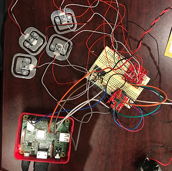
Image 8: The load cell and motor circuit attached to the Pi
Pre-Break Plans 11/21/19:
On Thursday, all eight of us went to the Forge Garden to connect the wiper motor to the 12V battery to see if the motor works. We all had to crouch behind the existing beehive to reach the motor and when we connected the motor directly to the battery the motor worked! However, we were still struggling to get the motor to run in the circuit. We tried to connect the external battery to the circuit, but it was too much power and we accidentally fried the H-bridge. I was able to get a new one from Dr. JAK and continued to play around with the motor.
On Friday, I met with Joce to give her the Arduino and load cells. Since she loves I the area, she was planning on testing the creep of the load cells over Thanksgiving break. We wanted to have that data to present in our findings.
Over the break Joce experienced a lot of issues with the Arduino. It wasn't allowing her to upload any code and she kept getting error messages. We think the Arduino must have also gotten damaged when we applied the external battery source.
This was a setback, because we could not collect any creep data which is information we wanted to present as a reason for our design.
Jack took the Pi with him over break, and he told us he was going to work with the code.
Final Presentation 12/5/19:
On the day of the final presentation, my team was rushing to make sure we could demonstrate the motor controlling the scissor jack. I had to run to the Engineering 1 Lab right before the presentation to get a new Dual H-Bridge since the other one was causing the Arduino to shut off every time it was connected to the circuit.
We were the first to present on Thursday. Phillip Krieg, our community partner was present and he was excited to see what we had to present. We had been in contact with him about the issues we faced, but he was understanding and still excited.
Our presentation went well and we got. lot of positive feedback from Phillip, Dr. JAK, and the class.
Unfortunately, our demo failed at the end of the presentation since some glue got stuck on the rubber band we had connecting the driving screw of the jack to the gear motor.
We were sure to include lots of information on what we recommend for the next team that will take on this project. My team is proud of the work we accomplished and are excited to see what the next team can do with the information we give them.
Our final presentation and final report can be found under "Formal Documents"
Self Reflection 12/10/19:
I am really proud of the work I accomplished this quarter. I learned so much about working on a team and addressing obstacles as they happen. My team communicated well with each other and I was proud of the work everyone accomplished.
After going through the Engineering process from start to finish, I look forward to taking what I have learned and apply it to future products and designs.
My individual reflection the project can be found under "Formal Documents".
Final Assembly of Prototype: